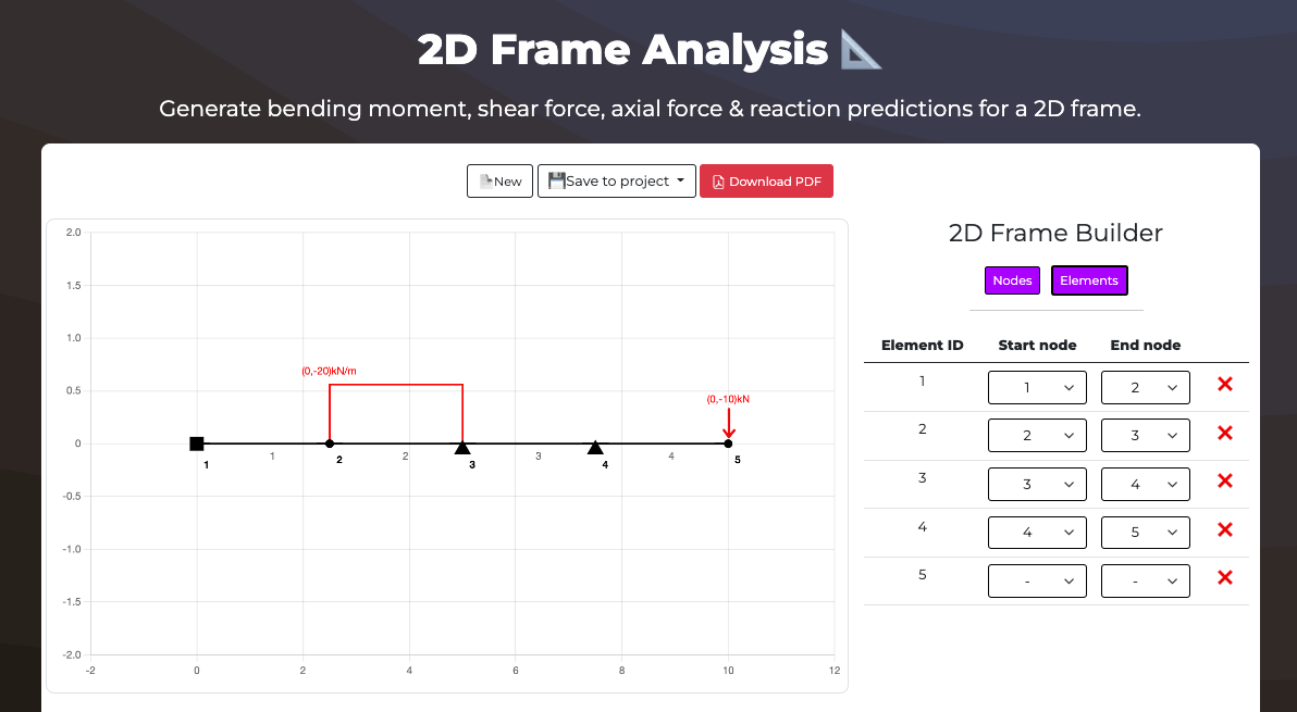
Free Structural Analysis Calculator
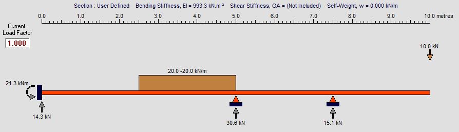
Generate bending moment diagrams, shear force diagrams and deflection for a 2D frame.
👷 Tip: Start adding nodes to enable other features.
| Node | X Coord | Y Coord | Restraint |
|---|---|---|---|
| 1 |
m
|
m
|
|
| 2 |
m
|
m
|
| Element ID | Start node | End node | |
|---|---|---|---|
| 1 |
| ID | Applied to type | Applied to Node | Position on element | Load (x) magnitude | Load (y) magnitude | |
|---|---|---|---|---|---|---|
| 1 |
|
%
|
kN
|
kN
|
| Load ID | Element ID | UDL X magnitude | End X magnitude | UDL Y magnitude | End Y magnitude | Start position | End position | |
|---|---|---|---|---|---|---|---|---|
| 1 |
|
kN
|
kN
|
kN
|
kN
|
%
|
%
|
Loading...
Loading...
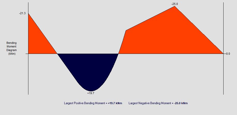
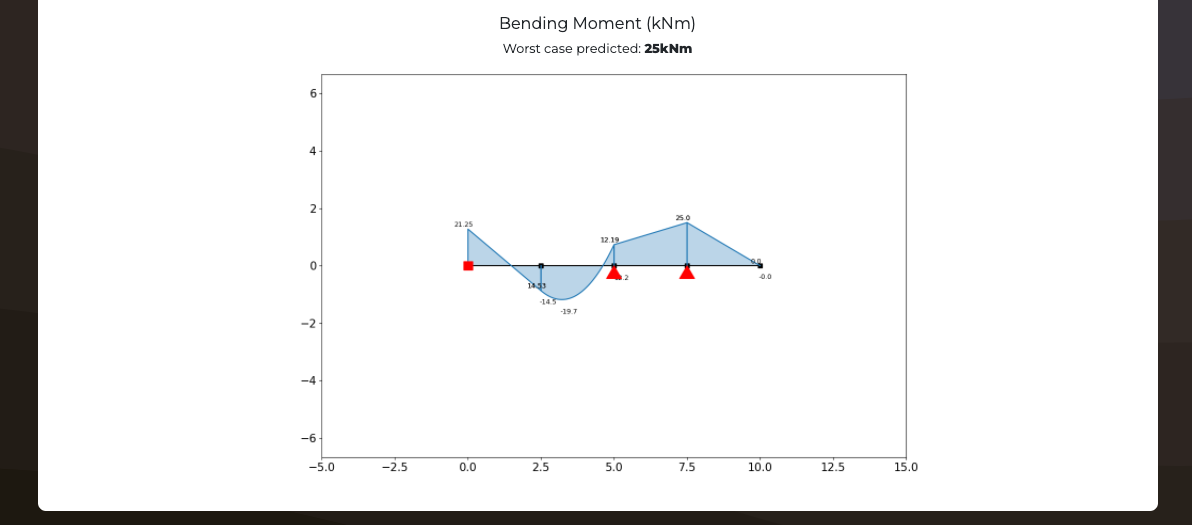
Bending moment result
Worst case predicted: kNm
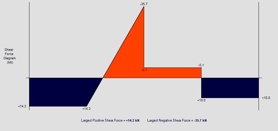
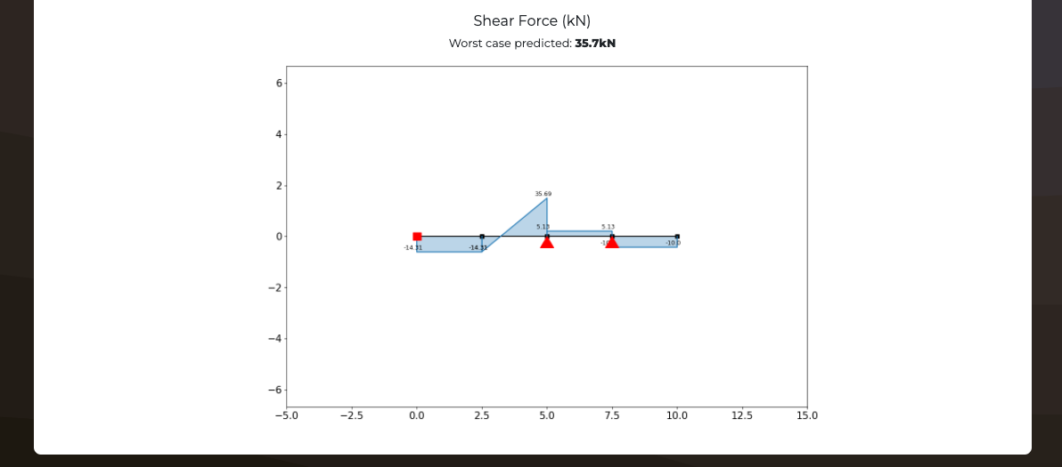
Shear force result
Worst case predicted: kN
Axial force result
Worst case predicted: kN
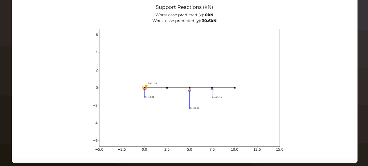
Support reactions result
Worst case predicted (x): kN
Worst case predicted (y): kN
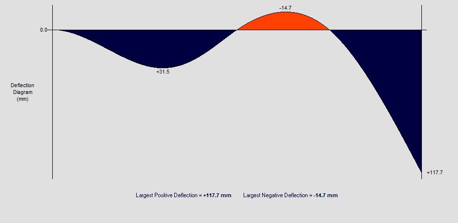
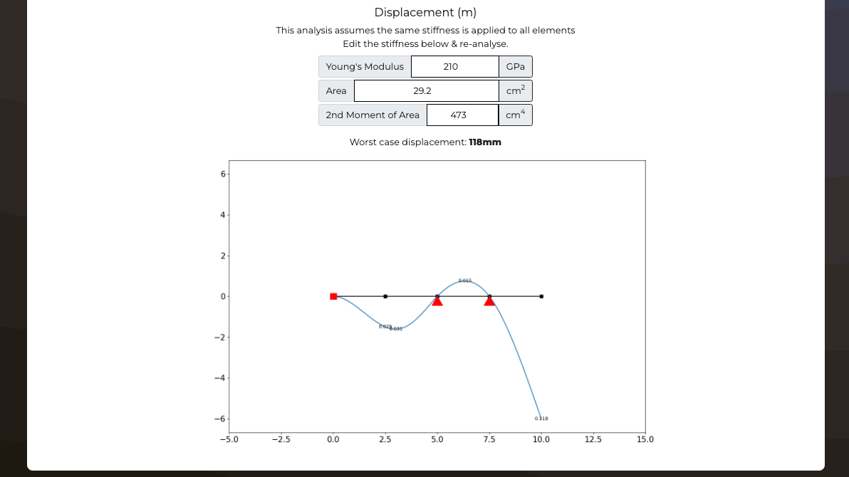
Displacement result
This analysis assumes the same stiffness is applied to all elements
Edit the stiffness below & re-analyse.
Young's Modulus
GPa
Area
cm2
2nd Moment of Area
cm4
Worst case displacement: mm
Analysis validation
What's this calculator used for?
This free Structural Analysis calculator can be used by Civil Engineers to design 2D frame structures. This tool will generate and find the bending moment, shear force, deflection and reaction forces on the structure. Add nodes and members with stiffnesses before applying point loads or distributed loads to the frame and calculating results. The frame can also be analysed as a truss structure rather than a pin jointed frame.
Contribute to this code
This code is open source and you can contribute to it's development.
You can find the source code on GitHub here: anaStruct
Special credits: Ritchie Vink
Are you interested in AI and automation in construction?
Import a structure
Click a structure type below to add a prebuilt template to this frame analysis


Frame calculator theory
What’s the difference between planar and 3D structural analysis?
- Most Engineering problems are 3D problems. Engineers however frequently simplify 3D problems into 2D or planar analysis. In the case of structural frame analysis often Engineers will perform 2D frame analysis along the x and y axis of the structure. If there are bi-axial effects which need to be considered on members resulting from this analysis, then these members can be analysed in isolation. 3D analysis is frequently on required for detailed design of complex models and often includes some element of dynamic analysis. Most analysis is usually simplified into 2D.
What’s the difference between determinate or indeterminate structures
- Determinate structures can be analysed using th simple equations of statics. For 2D structures this means that we can have no more than three unknown reactions since we only have three equations for 2D statics. Most problems found in CIvil Engineering are indeterminate problems. Indeterminate problems require approaches such as Moment Redistribution Theory.
What’s the difference between static and dynamic structural analysis in Civil Engineering?
- Static analysis considers forces applied to a structure which do not vary with time. In Dynamic analysis loads applied to the structure could vary in magnitude, location at which they are applied or both. Dynamic loading considers the inertia and damping of a structure.
What’s the difference between Linear or non-linear structural analysis?
- Linear analysis assumes that the applied load and deflection are proportional to one another. Most structures behave linearly within a certain range of loading. Non-linearity can result from material or geometric non-linearity or a combination of both.
What is Finite element analysis?
- Finite element analysis is used to break a complex shape into mesh of smaller interconnected elements which when combined represent the complete shape. Finite element analysis uses partial differential equations describing stress and strain relationships between the elements of the mesh. The calculations performed on each element are polynomial and involve interpolating the values. Determination of values starts at the boundaries of elements, known as nodel points. The calculations then propogate across all the elements in the mesh to arrive at estimated stress and strain values.