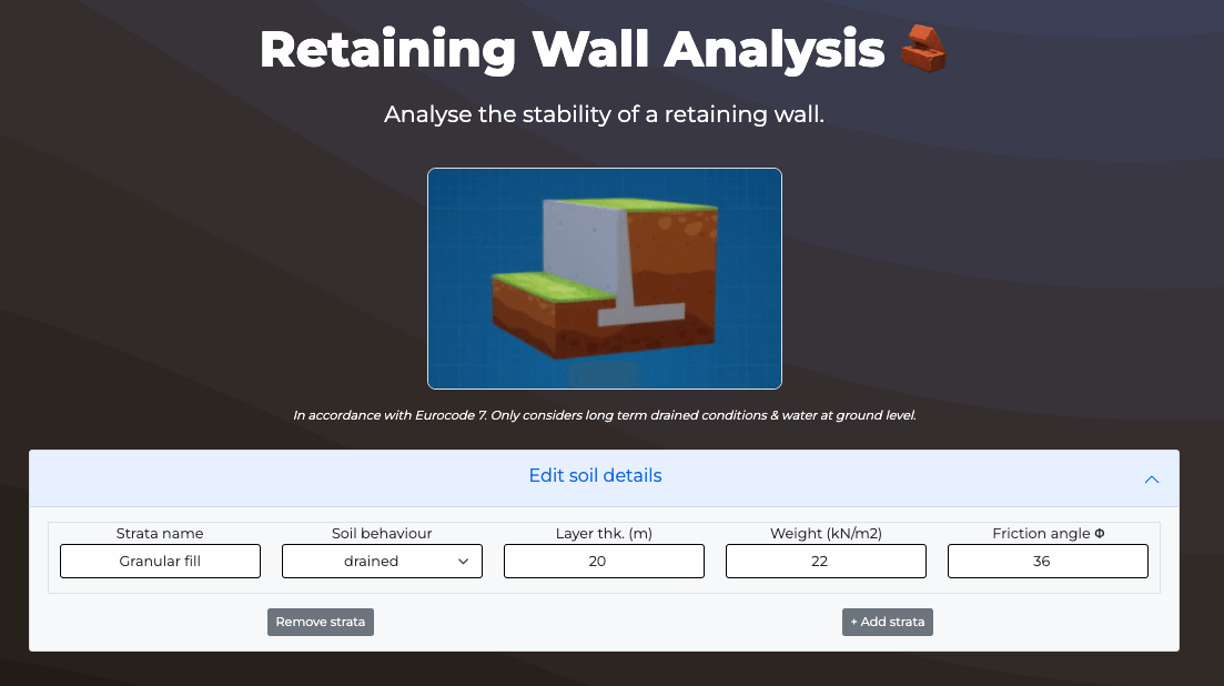
Free Retaining Wall Calculator
Design a concrete gravity wall and calculate stability.
Result
Utilisation
Earth Pressure Diagram
The benefitial effects of passive earth pressure are ignored
Results Summary
Loading...
Overall result:
Utilisation: %
This assessment doesn't include a structural assessment of the wall itself.
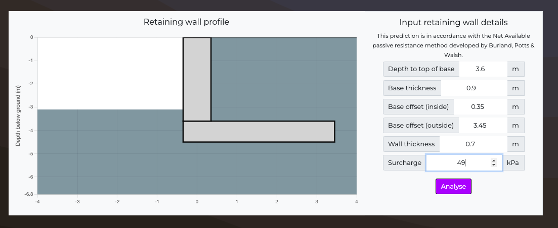
Retaining wall properties
Excavation depth
m
Depth > 7m not recommended. Check that base is within soil and above toe.
Base thickness
m
Max thickness of 3m & check that soil is deep enough.
Wall thickness
m
Max thickness of 3m.
Base length (inside)
m
Enter a thickness between 0 & 5m.
Base length (outside)
m
Enter a thickness between 0 & 5m.
Surcharge
kPa
Enter a number between 0 and 150.
Water table depth
m
Loading...
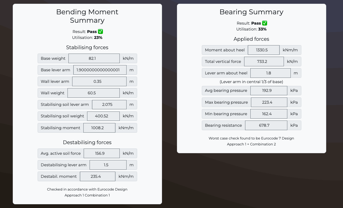
Wall Overturning Summary
Checked following Eurocode 7 Design Approach 1 - Combination 1
Stabilising forces
| Base weight | kN/m |
| Base lever arm | m |
| Wall lever arm | m |
| Wall weight | kN/m |
| Stabilising soil lever arm | m |
| Stabilising soil weight | kN/m |
| Stabilising moment | kN/m |
Destabilising forces
| Avg. active soil force | kN/m |
| Destabilising lever arm | m |
| Destabil. moment | kNm/m |
| Destabil. moment | kNm/m |
Overall overturning result:
Overturning utilisation:
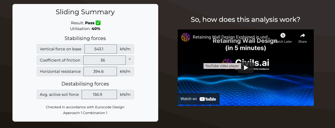
Wall Sliding Summary
Checked following Eurocode 7 Design Approach 1 - Combination 1
Stabilising forces
| Vertical force on base | kN/m |
| Coefficient of friction | o |
| Horizontal resistance | kN/m |
Destabilising forces
| Avg. active soil force | kN/m |
Result:
Utilisation:
Wall Bearing Summary
Checked following Eurocode 7. Worst case check found to be
Stabilising forces
| Moment about heel | kNm |
| Total vertical force | kN/m |
| Lever arm about heel | m |
| Avg bearing pressure | kN/m2 |
| Max bearing pressure | kN/m2 |
| Min bearing pressure | kN/m2 |
| Bearing resistance | kN/m2 |
Result:
Utilisation:
Retaining wall design theory
How are retaining walls designed?
Excavations and retaining walls are used to support earth pressure and create a cavity below the natural ground level. Retaining walls come in a wide range of shapes sizes and materials, retaining walls can include three components:
- Stem
- Toe slab
- Heel slab
Some walls may also include a sheer key to resist sliding
Stems can include drainage holes, these reduce the water pressure acting directly on the wall. A drain pipe can also be provided along the back of the wall for a similar effect. Coarse aggregate can be added along the back of the wall, this allows water to flow down to the drainpipe. The wall surface in contact with the soil is typically treated with some form of waterproofing.
Types of retaining wall
Gravity walls: These walls resist earth pressure via the self weight of the wall alone, typically these walls are constructed from stone masonry.
Cantilever walls: This is the most common type of retaining wall, these walls are typically used up to a depth of 8 metres below ground level. For this wall type the stem toe and heel act as one-way cantilever slabs. The stem acts as a vertical cantilever under the lateral earth pressure. The heel acts as a horizontal cantilever under the action of net weight of retained earth. The toe acts as a horizontal cantilever under the action of net soil pressure.
What are the possible slope failure modes
Overturning failure: In this failure mode the toe will act as the centre of rotation and the entire wall will rotate about this point, in the absence of the toe slab the base directly below the wall stem will act as the centre of rotation. The active earth pressure acts as a destabilising moment on the wall and the passive earth pressure acts as a stabilising moment. The weight of the soil on the heel slab will act as a stabilising moment.
Sliding failure: The active earth pressure applied to the wall acts as a destabilising force sliding the wall forwards, the stabilising force is provided by the friction between the base slab and the soil below. The frictional force is calculated by multiplying the friction coefficient between soil and concrete and the resultant soil pressure. If the active earth pressure is high and the wall is failing by sliding, then a shear key can be introduced to provide additional sliding resistance
Bearing failure: Bearing capacity is determined using the Terzaghi approach you can try our bearing capacity calculator below to learn more about this method.
How to calculate lateral and active earth pressure calculation
We first need to calculate the active and passive earth pressure with the following calculations:
- Pa = ½ * K a γ * H2
- Pa = ½ * K p γ * H2
Where ka is the active earth pressure coefficient, kp is the passive earth pressure coefficient, H is the depth of the excavation and γ is the unit weight of the soil.
The active earth pressure coefficient, ka is calculated as follows:
- ka = tan2(45-ϕ/2)
The passive earth pressure coefficient, kp is calculated as follows:
- kp = tan2(45+ϕ/2)
Where ϕ is the angle of friction or angle of repose for the soil.
Stability calculations
Horizontal forces acting on the active side of the wall are calculated using the earth pressures calculated above.
Moments are resolved as stabilising and destabilising moments acting on the surfaces of the wall. If an overhang of the retaining wall base exists then the stabilising force of soil self weight above this overhang can be considered.
Passive forces acting on the wall can be calculated as stabilising forces or moments, however some movement of the wall is required to fully mobilise these forces and therefore it is conservative to exclude the benefit of passive forces from the calculation.
The presence of an additional surcharge should be considered. This surcharge contributes to active earth pressure, the nature of the surcharge can for example result from vehicles or construction operations.
What's this calculator used for?
This free retaining wall calculator can be used by Geotechnical Engineers to design retaining walls and gravity walls. Calculate wall stability in terms of overturning moment, sliding forces & bearing capacity from lateral earth forces in accordance with the European regulations (Eurocode 7). This calculations only considers long term drained conditions and the ground water level at ground surface level. This retaining wall design follows the limit state approach.
Are you interested in AI and automation in construction?