Free Truss Analysis Calculator
Calculate axial forces, reactions and displacement of a roof truss or floor truss structure.
👷 Tip: Start adding nodes to enable other features.
| Node | X Coord | Y Coord | Restraint |
|---|---|---|---|
| 1 |
m
|
m
|
|
| 2 |
m
|
m
|
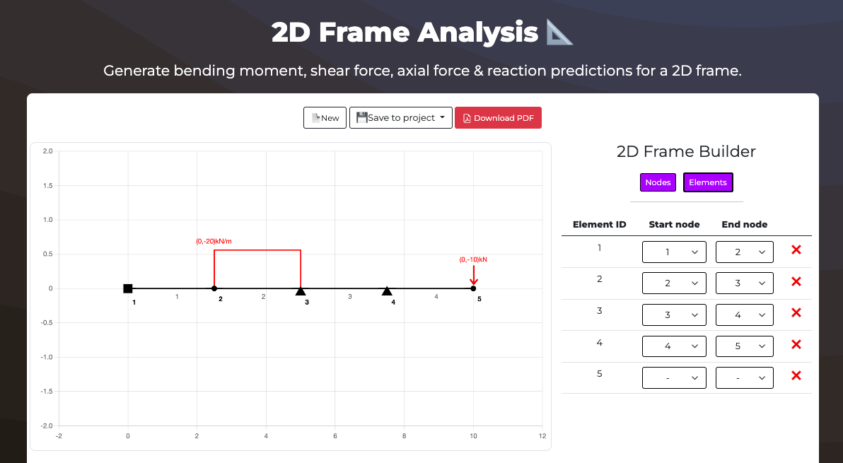
| Element ID | Start node | End node | |
|---|---|---|---|
| 1 |
| ID | Applied to type | Applied to Node | Position on element | Load (x) magnitude | Load (y) magnitude | |
|---|---|---|---|---|---|---|
| 1 |
|
%
|
kN
|
kN
|
| Load ID | Element ID | UDL X magnitude | End X magnitude | UDL Y magnitude | End Y magnitude | Start position | End position | |
|---|---|---|---|---|---|---|---|---|
| 1 |
|
kN
|
kN
|
kN
|
kN
|
%
|
%
|
Loading...
Loading...
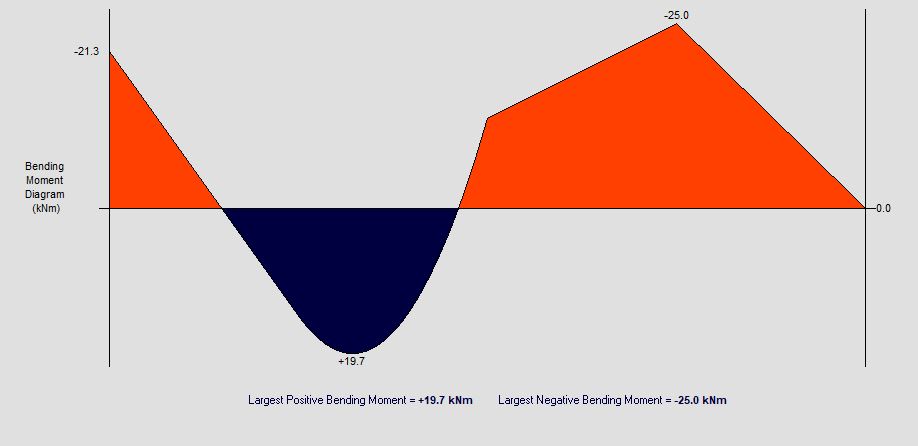
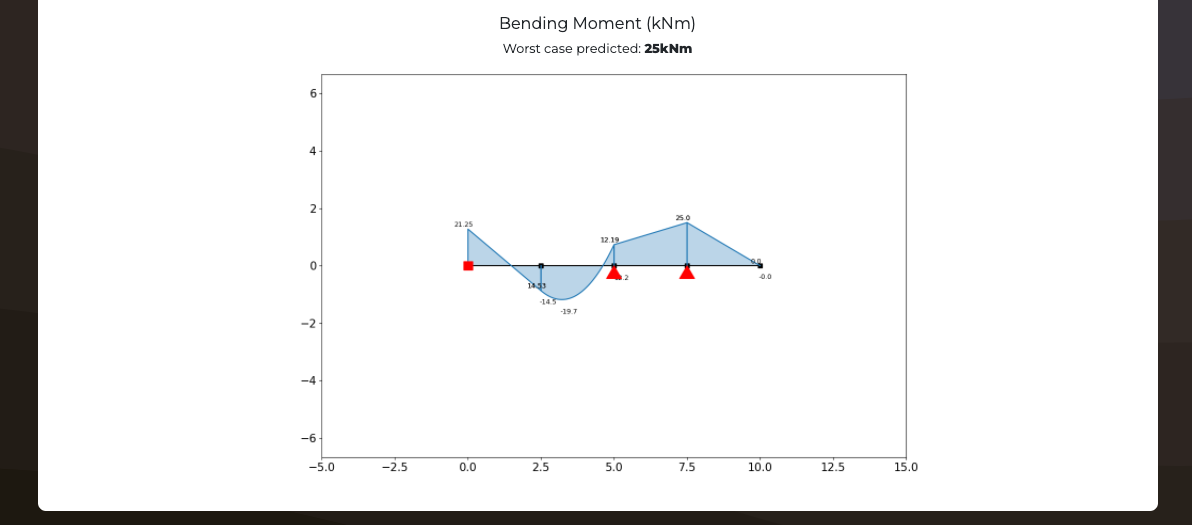
Bending moment result
Worst case predicted: kNm
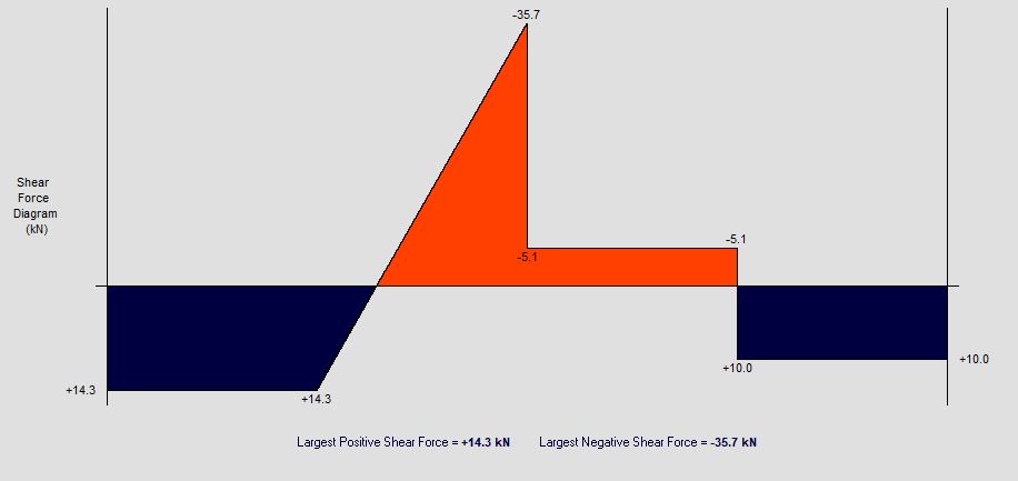
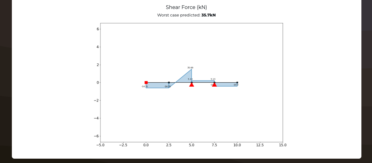
Shear force result
Worst case predicted: kN
Axial force result
Worst case predicted: kN
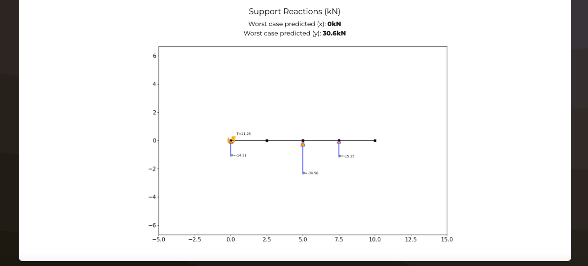
Support reactions result
Worst case predicted (x): kN
Worst case predicted (y): kN
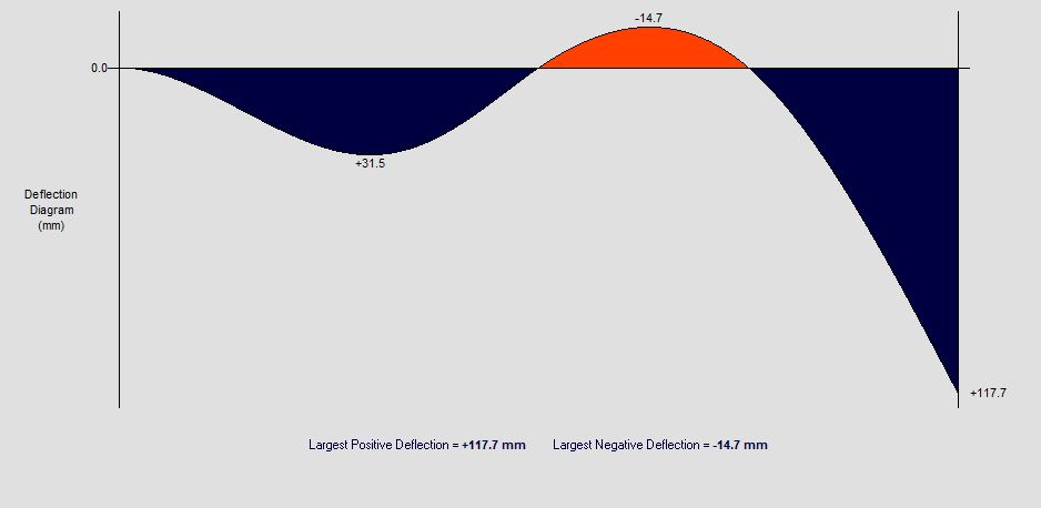
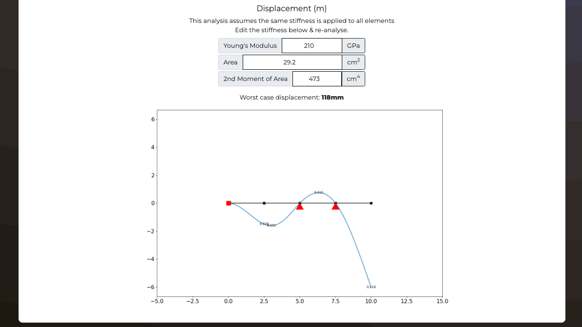
Displacement result
This analysis assumes the same stiffness is applied to all elements
Edit the stiffness below & re-analyse.
Young's Modulus
GPa
Area
cm2
2nd Moment of Area
cm4
Worst case displacement: mm
Analysis validation
What's this calculator used for?
This free online roof truss calculator can be used by Civil Engineers for structural truss design. Generate the axial forces, reactions and displacements for each node of the structure. Customize the layout of the truss and use it as a roof rafter calculator, wood truss calculator, scissor truss calculator and roof framing calculator.
Contribute to this code
This code is open source and you can contribute to it's development.
You can find the source code on GitHub here: anaStruct
Special credits: Ritchie Vink
Automatically check your designs against building codes
Discover how you can use algorithmic checking on your construction project documents.
Get access to our full software suite including our 7 module online AI in Construction Certification.
Import a structure
Click a structure type below to add a prebuilt template to this frame analysis


Truss calculator theory
What are trusses?
- Trusses are structural frameworks composed of straight members connected at their ends to form a stable and rigid structure. They are commonly used in engineering and construction to support roofs, bridges, and other structures. Trusses are designed to efficiently distribute loads, such as the weight of the roof or the bridge deck, to the support points, which are usually the walls or columns.
What is the difference between a truss and a frame?
- Trusses are structures typically arranged as a series of elements connected in triangular patterns. The connections between individual elements typically do not carry any moment or shear forces, instead the elements only transfer axial forces with the forces eventually resolving as reactions into the truss supports. This results in trusses being less flexible than frames but are often cheaper, more lightweight and more efficient to construct. Meaning that trusses are commonly used in roofing, flooring and bridges.
What is a roof truss?
- A roof truss is a structural framework designed to support the roof of a building. It is one of the most common methods used in modern construction for residential, commercial, and industrial buildings. Roof trusses are typically triangular in shape and consist of straight members connected at joints..
How to design roof truss?
-
Design of a roof truss is one of the most common design requirements during home building, this is a list of the most common steps in designing a roof truss:
- Determine the roof's span, pitch, and load requirements.
- Select appropriate materials for the truss based on the load and aesthetic preferences.
- Calculate the forces acting on the truss members using structural engineering principles.
- Choose a suitable truss configuration (e.g., king post, queen post, Howe, etc.) based on the design requirements.
- Use engineering software or manual calculations to analyze the truss and ensure it meets safety standards.
- Adjust the truss design if necessary and reanalyze until it meets all safety and load-bearing criteria.
- Get the design checked and approved by a qualified structural engineer.
- Fabricate the truss components and assemble them according to the approved design.
- Install the truss securely on the roof structure following construction guidelines.
Truss solver
- To solve trusses follow the following steps:
- Analyze the forces: Break down the truss into its individual members and joints. Identify all the external loads and reactions acting on the truss.
- Apply equilibrium conditions: Apply the principles of static equilibrium (sum of forces and moments equal to zero) to each joint to determine the internal forces in the truss members.
- Solve for member forces: Use methods like the method of joints or method of sections to calculate the forces in each truss member.
- Check for stability: Ensure the truss remains stable under the applied loads by verifying that the internal forces in the members satisfy the strength and stability criteria.
- Design verification: If the truss is part of a structure, verify that the members' dimensions and materials meet the design requirements and safety standards.
- Iterate if necessary: If the truss fails to meet the design criteria or stability requirements, make appropriate changes and reiterate the analysis until a suitable solution is achieved.
Rafter calculator
- Rafters are a fundamental component of a roof structure in building construction. They are sloping beams that support the roof and transfer its weight to the walls or other structural elements of the building. Rafters typically run from the ridge or the highest point of the roof down to the eaves or the edges of the roof. Rafter truss calculators have a range of applications most commonly being used as a roof truss calculator, a wood truss calculator, roof rafter calculator, scissor truss calculator, attic truss calculator, or for roof framing.
What are the different types of truss?
-
Trusses come in a wide range of shapes and sizes however some of the most common types are listed below:
- King Post Truss: Simple truss with a single vertical member in the center, connecting the apex of the top chord to the midpoint of the bottom chord.
- Queen Post Truss: Similar to the king post truss but with two vertical members.
- Howe Truss: A truss with diagonal members slanting towards the center and vertical members at the ends.
- Pratt Truss: Opposite of the Howe truss, with diagonal members slanting outward and vertical members at the center.
- Warren Truss: A truss with diagonal members alternating in direction, creating a zig-zag pattern.
- Fink Truss: A type of Warren truss with additional internal bracing.
