AI for Cable Tray Takeoff: Trunk/Branch Lengths & Accessories

Why Estimators Use AI Assistance
Save precious time
Reduce hours spent searching through drawings and schedules so you can concentrate on pricing and strategy.
Keep numbers traceable
Draft outputs point back to the source documents, making reviews and clarifications easier with your team and clients.
Stay flexible
Addenda and changes happen. It’s simpler to update and re-issue a takeoff when the groundwork is already prepared for you.
Upload PDFs and run a simple prompt. A draft takeoff is prepared and you are notified when processing is completed.
How It Works
- Upload your PDFs — Add MEP plans, single-line schematics, tray schedules and any notes you want considered.
- Write your prompt — Tell Civils.ai what you need (for example: “Measure cable tray trunk and branch runs by tray size/system; count fittings & accessories; list supports/hangers at the noted spacing; split results by floor/area”).
- Click “Run” — The platform begins preparing a draft takeoff based on your uploaded drawings and schedules.
- QA review & adjust — Your QA team reviews the draft, fixes any issues, and confirms assumptions (e.g., support spacing, routing choices) before release.
- Share with confidence — Release the reviewed drawing set and quantities to your stakeholders with clear references back to the source PDFs.
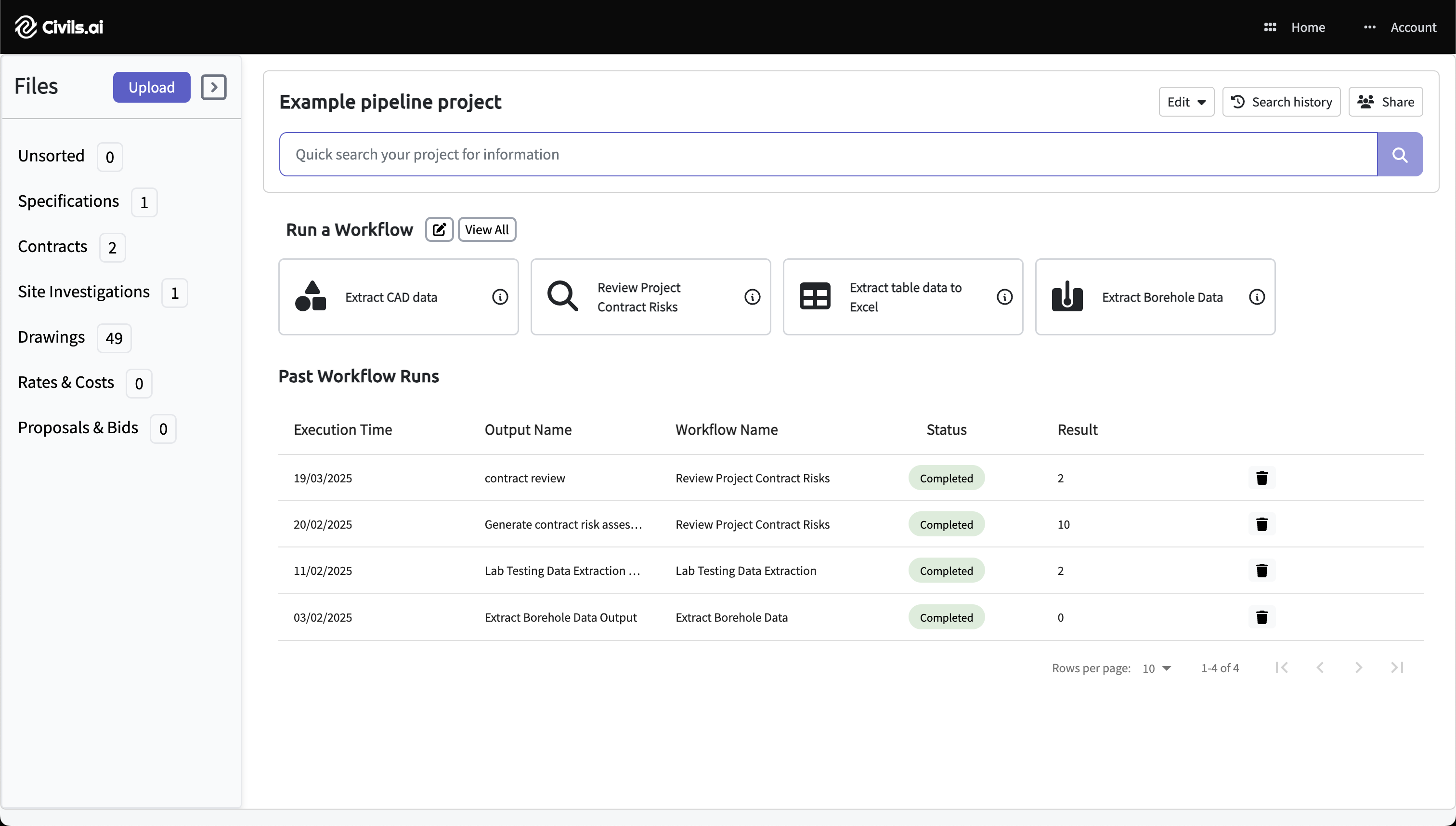
Upload PDFs
Drag & drop your drawing or document PDFs and select Extract CAD data. Works with scanned, historic and multi-sheet drawings.
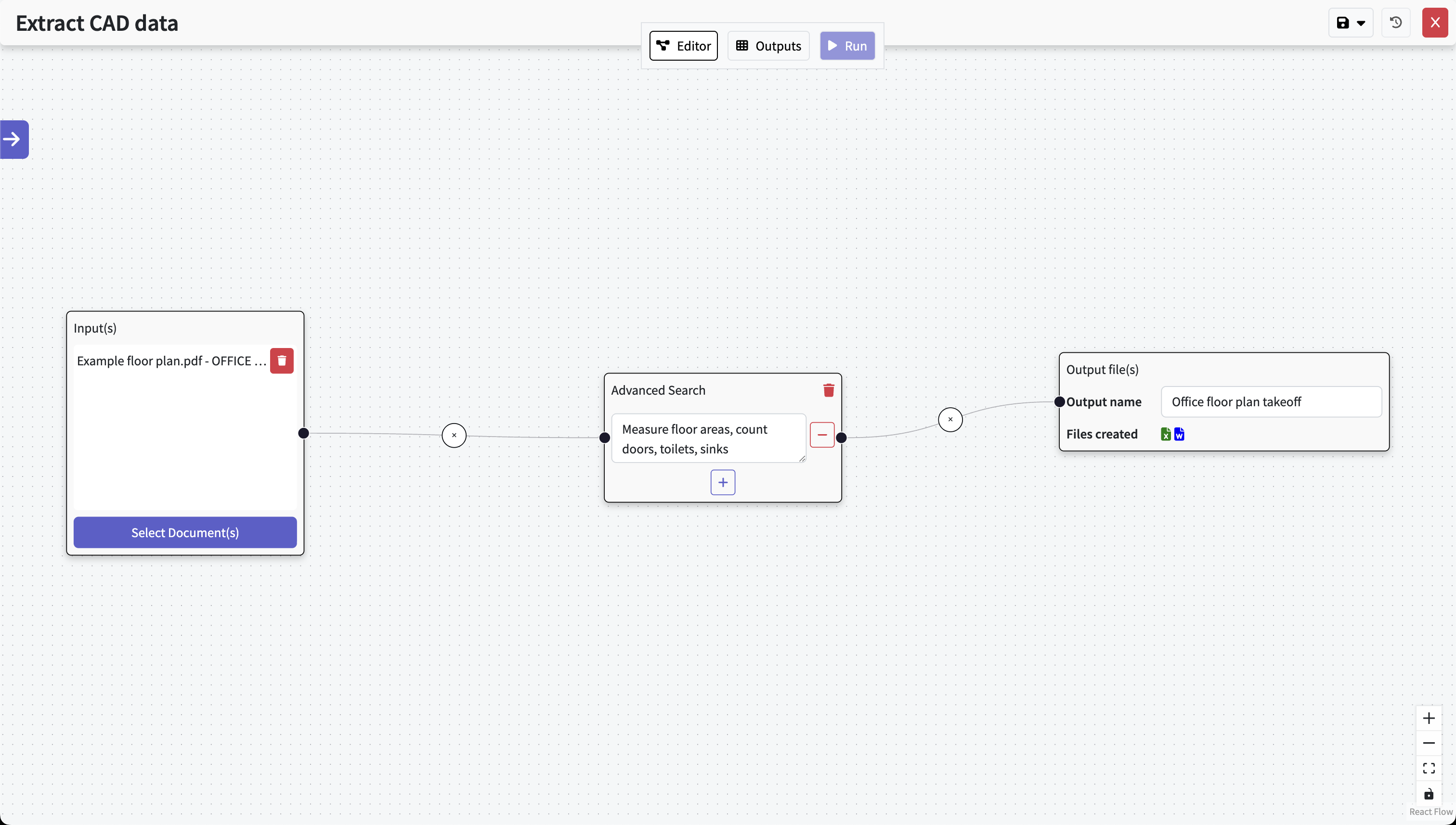
Type out your prompt
Type what you need in natural language (e.g. “measure cable tray trunk & branch lengths by size/system; count elbows, tees, reducers, crosses & drops; list supports/hangers at 1.5 m spacing”). Hit Run and the AI performs the takeoff and our QA team reviews the results.
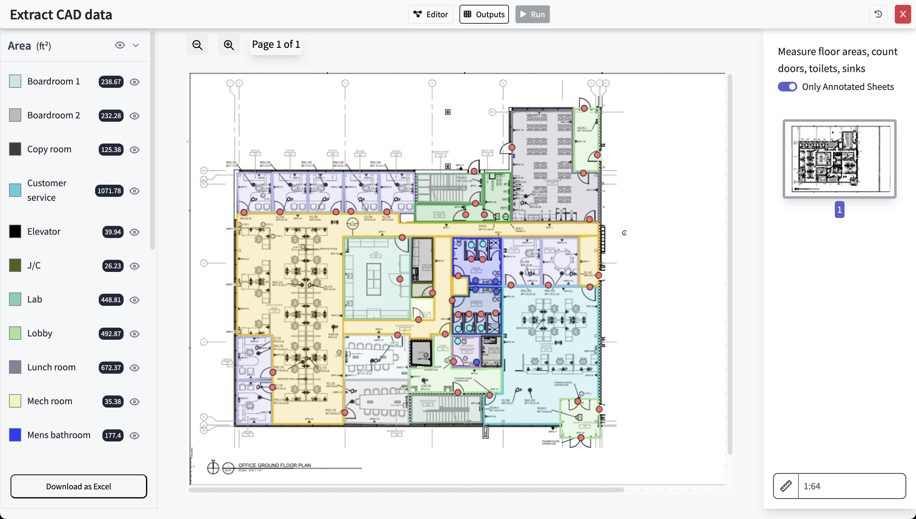
Get results, review & export
What the Draft Takeoff Can Cover
The goal is a clean starting point for pricing—prepared from your drawings and schedules—so your team spends more time refining and less time starting from scratch.
Typical items
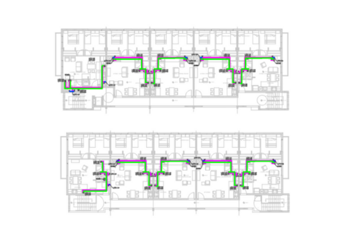
- Trunk & branch linear lengths by tray size/system and floor/area
- Fittings & accessories: elbows/bends, tees, crosses, reducers, drops/risers, couplers, covers
- Support/hanger counts based on spacing assumptions you specify (e.g., 1.5 m)
Clarity on assumptions
Tray sizes and routes are taken directly from your drawings/schedules. Measurements follow the path centerline. Vertical risers are counted when explicitly shown. Support spacing follows your prompt/specs; otherwise, assumptions are called out for QA.
What to Expect (and What Not To)
Overview
What you can expect
- A prepared draft takeoff to help your bid
- Clear references back to the drawings and schedules
- Faster internal reviews and fewer back-and-forths
Limitations to note
- Not a 100% automated takeoff—human review is essential
- No 3D clash detection or coordination output
- No inference of tray sizes beyond what is shown
- Pipework
- Ductwork
- Cable tray
- CHWS
- CHWR
- CHWP
FAQ
Is this suitable for busy bid periods?
Yes. It prepares a draft quickly so your team can review, adjust, and price with confidence instead of starting from a blank page.
Can we trust the numbers?
Use the draft as a starting point. Your QA team checks and fixes anything that needs attention before releasing numbers to stakeholders.
Where do the quantities come from?
From the PDFs you upload—plan drawings, single-line schematics and tray schedules. Everything stays traceable to the source pages for easy review.
What about risers or 3D routing?
Vertical risers are measured when explicitly shown. 3D coordination/clash detection is out of scope; use the draft to guide pricing, then finalize with your team’s review.
AI for Cable Tray Takeoff: Trunk/Branch Lengths & Accessories
Upload your drawings and schedules, write a quick prompt, click run—then let your QA team review and release a clear, traceable cable tray takeoff.
Civils.ai is an assistive tool for bid preparation. Final quantities and assumptions should be reviewed and approved by qualified professionals.